The Laser
Camera
See the workpiece under the design: camera alignment, material heights, lens calibration, several cameras and analysis of the engraved result.
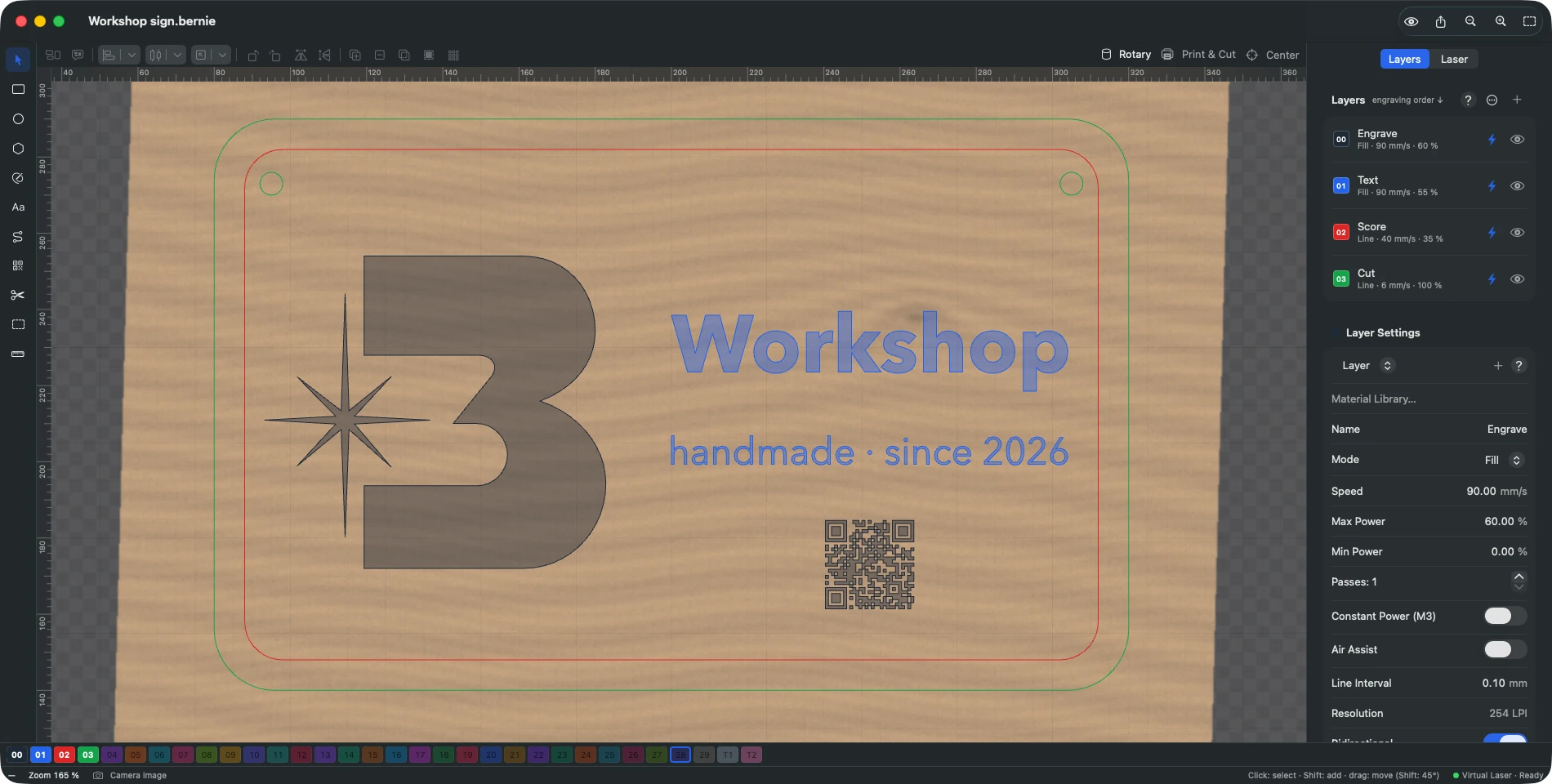
Laser › Camera… shows the image of the bed under the design, in its real place: to put a design on a piece that is already on the machine. Three sources: Head-mounted camera: for a camera fixed to the head, which moves with it and only sees a small area, check Camera Mounted on the Head and set the camera field of view (shorter side of the area seen, in mm). Alignment, once: with the laser connected, bring the head above a plate, Add Head Target (four coded markers around the head, on a new layer), engrave it without moving the head, then Align on Target. Then Update Image scans the selection (otherwise the whole bed): the head moves, stops, one shot at each position (“Shot 3 of 12”), then the shots are stitched under the design — each point comes from the shot where it is closest to the image centre. In Bernie Studio, the same section is in the Camera tab (webcam fixed to the head, laser connected in the Laser tab).
USB camera (the laser’s), network camera (address of a still image or an MJPEG stream: IP camera, ESP32-CAM) or a bed photo taken with a phone, straight down and always from the same spot (fixed mount).
- Align Camera… (once, or after moving the camera). Automatic (default): Add the coded markers to the project (nine coded squares, on a fill layer), engrave them on a flat plate without moving it afterwards, then Take Image and Align: Bernie finds the markers by itself (at least 3 visible; those found are marked on the image) and aligns the camera. Manual: Add the 9 marks to the project, engrave these crosses, Take Image, then click the center of each cross in order (left to right, top to bottom). The accuracy is shown (under 1.5 mm: good alignment); with at least 6 points, lens distortion is corrected too. Save.
- Update Image: a new shot, aligned under the design. Opacity sets its transparency, Hide removes it. The image is never engraved. X / Y Offset fine-tunes its position without redoing the alignment, Image Width / Height (in %) corrects its scale around the bed center, Image Resolution sets its sharpness (automatic, 1, 2, 4 or 8 pixels per mm); Save Bed Image… keeps it as a PNG; Continuous Update takes a new image at regular intervals while the panel is open. When Panel Opens: nothing, Update Image or Continuous Update (aligned camera). Captures: size and weight of the last image, capture time (and average), possible rate, shots and failures — to judge a network camera or its Wi-Fi. Material Height: each workpiece thickness has its own alignment (the image of a thick piece is larger and shifted) — Add a Height…, place a piece of that thickness and align the camera on it; then pick the height of the piece on the bed. Export Alignments… / Import… carry them to another computer, with the lens calibration (distortion, mean error, number of shots and date, shown in Calibrate Lens…). Brightness, Contrast and Saturation lighten the image or make the workpiece stand out under the design (the image is never engraved).
- Insert Image Into Project: the aligned image becomes a project image (covering the bed), to trace or engrave.
Analyze the Result (Camera panel, or Laser › Analyze the Result (Camera)…; Bernie Studio: Camera tab): after the job, update the image (or choose a photo of the bed); Bernie compares it with what the job was meant to engrave, for the whole job or only the selection. The comparison image shows the photo and, in red, the expected outline. The findings: similarity and contrast (dark or light marks), engraving offset (to 0.1 mm, within the image’s precision), engraving offset from the cuts (the part moved), wrong size in X or Y (steps per mm), skewed result (gantry out of square), regular bands with their pitch (pulley, belt, bearing: a 20-tooth GT2 pulley travels 40 mm per turn), uneven tone and the stronger side (focus), fill that did not mark. Each finding gives its likely cause and opens My Job Is… on that symptom. If the job was placed correctly, Realign the Camera Image corrects the image offset (the panel’s X and Y Offset).
Several cameras
The panel’s Manage menu adds a camera, renames or deletes it; each one keeps its source, its alignments and its image settings. Link to Device puts it in use by itself when that device becomes active. The Cameras list (as soon as there are several, or while the camera is not aligned) shows each one’s status: Source set, Aligned, Image received (camera in use) — a red dot is fixed with a click (camera choice, alignment, diagnosis); a click on the name puts the camera in use. Global image: a camera’s eye includes it in the global bed image; with at least two cameras included, Update Image takes one image per camera, maps it with its own alignment (for the current material height) and overlays them — to cover a large bed with several cameras. A camera without an image or alignment is reported and skipped; a bed photo only serves the camera in use.
USB camera
Resolution (automatic, 720p, 1080p, 4K; changing it requires realigning) and warm-up frames (skipped when the camera opens while the exposure settles: more if the image comes out dark). Keep the last image between sessions puts the bed image back under the design when a project opens, without a new capture. Forget the Alignment for This Height removes an alignment that has become wrong. Interpolate Between Aligned Heights (on by default): a height without an alignment gets one computed from the two nearest aligned heights (marked “interpolated”). No Image? Diagnosis… checks the permission, the cameras seen by macOS, the chosen camera, the alignment and the last error, with what to do (Bernie Studio: secure page, site permission, cameras seen). Choose a Lens… (also Help › Camera Selection Help…) computes the field of view needed to see the whole area from the camera height, and checks a camera from its stated angle (diagonal, width or height): area seen and sharpness in pixels per mm. Calibrate Lens… (wide-angle camera): Add Target to Project (nine coded markers over 160 × 120 mm), engrave it on a flat, rigid board, place it at various spots in the camera’s view (corners and edges especially), taking an image each time, then Calculate: four correction models are computed — Simple (most webcams), Extended (strongly distorting wide angle), Fisheye (real fisheye lens only), No correction (camera that straightens its own image) —, each with its mean error; the recommended model is selected for you. The preview shows the latest shot straightened under a straight grid: choose the model that makes straight lines straight, especially in the corners, not necessarily the smallest error. Each shot’s error is shown; a shot clearly worse than the others is flagged “retake” and can be removed. After Save, the model is kept for this camera. Later alignments only have to place the image, which is more accurate at the edges. Redo it only when changing the lens or the resolution.
The camera is used only when you ask (one image at a time); macOS asks for permission the first time.
Which camera? A UVC-compatible USB camera (recognized without a driver), fixed above the bed so it no longer moves: wide-angle lens to see the whole bed, 1080p or more. The higher and more centered it is, the less the image is distorted. Without a camera: a phone photo, always taken from the same spot (fixed mount), gives the same result for placing a design on a piece.
This manual is also built into Bernie: press F1, or open the Help menu, to read the topic for what you are doing. A mistake, a missing answer? Tell us
Try it in Bernie, for free.
Free laser engraving and cutting software for diode, CO2, fiber and galvo lasers. Windows, Mac, Linux, iPad, iPhone and in the browser.