The Laser
Galvo Lasers
Galvo device settings, laser source, rotary and external axis, live framing, lens calibration and cylinder correction, simulated by the virtual galvo, and JCZ boards driven directly.
A galvo laser (fiber, MOPA, UV, CO2 galvo) has no moving head: two mirrors steer the beam within the field of a lens (110 × 110 mm, 175 × 175 mm…). Settings › Devices › New › “Galvo fibre 110 × 110 mm”, or the Galvo laser box of a profile: the width and height become those of the field, Bernie’s workspace.
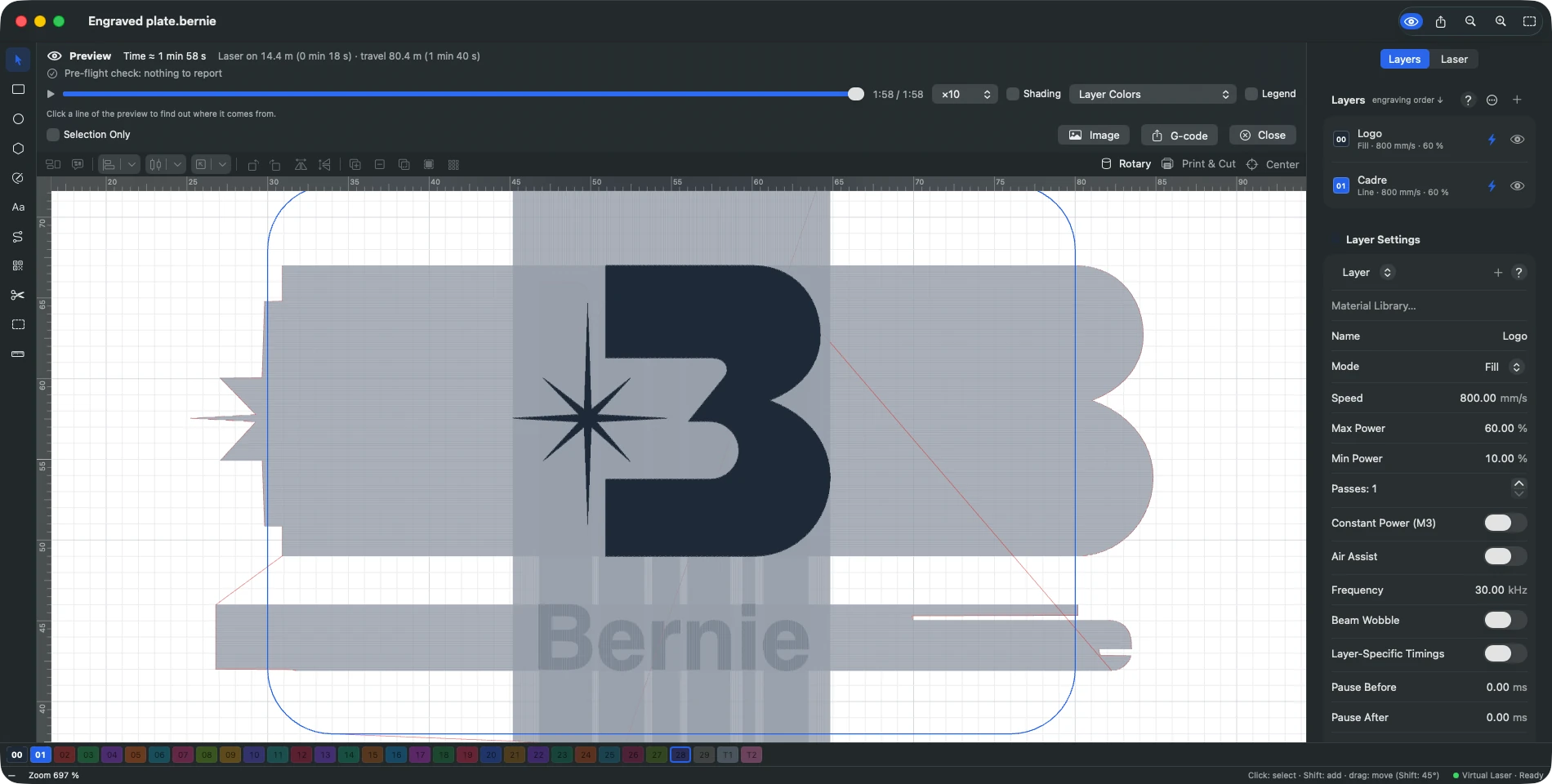
- Galvo laser: source (fiber, MOPA, UV, CO2), field offset and head rotation, mirror driving the X axis, direction and scale of each mirror.
- Jumps and delays: jump speed and wait after a jump (longer for a long jump), laser on, laser off, end and corner delays (µs) — too short or too long, they leave burnt or missing marks at line ends and corners; framing and maximum speeds.
- Lens corrections: bulge, skew and trapezoid of each mirror, from -1 to 1.
- Laser source: depending on the type (fiber, MOPA, UV, CO2, SPI) — allowed frequency range (PWM modulation can be turned off for a CO2), adjustable pulse width and master oscillator of a MOPA, tickle pre-ionization and first pulse killer of a CO2, pulse bounds of a UV, simmer current of an SPI, second source (selection port, analog output; each layer can then choose Laser source 2). Values to copy from EZCad or the manufacturer’s data. The virtual galvo flags layers whose frequency or (UV) pulse width falls outside these ranges.
- Rotary (Laser panel, Settings…): to mark all around a cylindrical object on a rotary, the design is cut into slices; the rotary brings each slice under the lens, the galvo marks it, then moves on to the next. Settings: rollers or chuck, motor steps per rotation, roller and object diameters (linked circumference), axis along which the object unrolls (X or Y), slice width (small: fewer defects on a tapered object; large: faster) and overlap (extra length hiding the seams, useful to remove paint, best avoided for direct marking), mark whole shapes if possible (up to a maximum size: the shape is marked in one go, the rotary centered on it), order (all shapes in each slice, never going back, for rollers; or the job order, for a chuck), output center (line of the field under which slices are marked; 0: the middle), motor speeds, direction and return to start. The center line of the workspace is the rotary’s starting position: the farther the design is from it, the more the object turns before marking. The virtual galvo gives the number of slices, the rotation and its time (included in the duration), shows each slice as it is marked (‹ Slice n / N ›) and flags a slice narrower than one motor step, fill lines that would cross the slices (set them parallel to the object’s axis: 0° if the object unrolls along Y, 90° otherwise) and a layer that fills all its shapes at once while they must stay whole.
- External axis (Laser panel, Settings… of “Split marking”): linear table (X or Y orientation) or rotating table driven by the board — pulses per turn, travel (mm) or axis turns per motor turn, speeds, direction, return to start. Split marking (linear table): a design larger than the field is marked slice by slice, the table bringing each one under the lens (same slice settings as the rotary). Repeat marking: the same job several times, the table moving forward between two markings (mm, or degrees for a rotating table; Calculate gives 360° / count for evenly spaced positions), with a pause to let it settle — batch production, often with variable text. The external axis waits until the rotary is off. The virtual galvo gives the slices or markings, the table moves and their time. Import an EZCad Configuration (markcfg, Motors.ini)… (galvo device settings; Bernie Studio: “EZCad Configuration” section) reads a file from EZCad’s
PARAMfolder. EZCad2 (markcfg0tomarkcfg7, the one of the board in use): field size (work area), field offset and rotation, mirror driving X, reversed directions, scales, lens corrections (bulge, parallelogram turned into skew, trapezoid: 1 in EZCad, 0 in Bernie — check them with a calibration grid, as EZCad does not publish its formulas), frequency range of the source; extended axes and the red pointer offset are reported, to set up by hand. EZCad3 (Motors.ini): the linear table it names becomes the external axis (pulses and travel per turn, direction, speeds, acceleration), the A axis sets the rotary. - Live framing (Laser panel): the red frame follows the selection while you place the part. Next style goes from bounds to hull then to contour. With the keyboard (Mac, Bernie Studio) or the buttons: arrows 5 mm (Shift 20 mm, Option 0.5 mm), “.” and “,” rotate by 15° (Shift 1.5°, Ctrl 45°), PgUp and PgDn enlarge or shrink by 5 %. Frame before marking (device setting, on by default): the first “Mark” opens live framing, the second starts the marking. While marking: Pause / Resume and Stop.
- Mark (Laser panel, simulation): the virtual galvo “marks” the job for the computed time (10 s at most, accelerated beyond) then counts the piece. Pieces and Reset; Repeat (the job this many times in a row — to repeat only some layers: passes or global passes); Run continuously (restarts at the end of each piece, for deep engraving; turning it off stops at the end of the current piece); Stop at count (no more starts once this number of pieces is reached); Stop interrupts the current piece, which is not counted. Layer setting Auto-rotate from one piece to the next (fill): each new piece starts turned by one more angle increment, so successive markings do not overlap line by line; resetting the counter restores the starting angle.
- Calibrate Lens (Laser panel button): a one-window assistant. Test pattern: nine crosses and a letter F, centered in the field (suggested size: 85 to 90 % of the field), added to the active layer — mark it on a contrasting material. Orientation: pick, among eight, the letter F as it came out (the pattern in front of you as on screen); a mirrored or rotated output fixes the X-axis mirror and the mirror directions. Measurements: from cross center to cross center, the three rows, the three columns and the two diagonals. Result: scale, bulge, skew and trapezoid of each mirror, computed and saved in the device by Apply; Maximize working area extends the field up to the travel of the mirrors if the lens covers more (power may drop at the edge). A second pattern refines the corrections. Mark the pattern with the galvo board driven directly (experimental) or with the machine’s software.
- Cylinder correction: to mark a cylindrical object lying flat, without a rotary (glass, tumbler, pen). The design wraps around the surface — a length of the design across the object becomes an arc of the same length — and each point is aimed where the beam meets the surface. Settings: object diameter, mirror distance (from the mirrors to the focus plane: the lens focal length plus the height of the mirrors above it, not the focus distance), cylinder axis (parallel to X or Y), concave surface (inside of a ring, a cup). Center the design on the object and focus on its top (the bottom, if it is concave); beyond a quarter turn on either side, the surface can no longer be reached: the virtual galvo counts these points, brought back to the edge. The Cylinder correction switch of the Laser panel turns it on or off without opening the settings.
- Layers (galvo device): pulse frequency (kHz), pulse width (ns, MOPA sources) and beam wobble — the spot moves in circles of the chosen diameter along the path, one per set advance: wider line, cleaning, welding (no corner delay). Dot width (fill): each line is shortened by half of it at each end, for clean edges despite the spot size. Layer-specific timings: the layer’s own jumps and delays instead of the device’s (starting from the device’s values); pause before and pause after (ms), for example to let the part cool down between two layers.
- Galvo Board, experimental: EZCad2 JCZ “LMC” boards, connected over USB (Mac, Bernie Studio in Chrome or Edge, desktop app) or to Bernie Link (
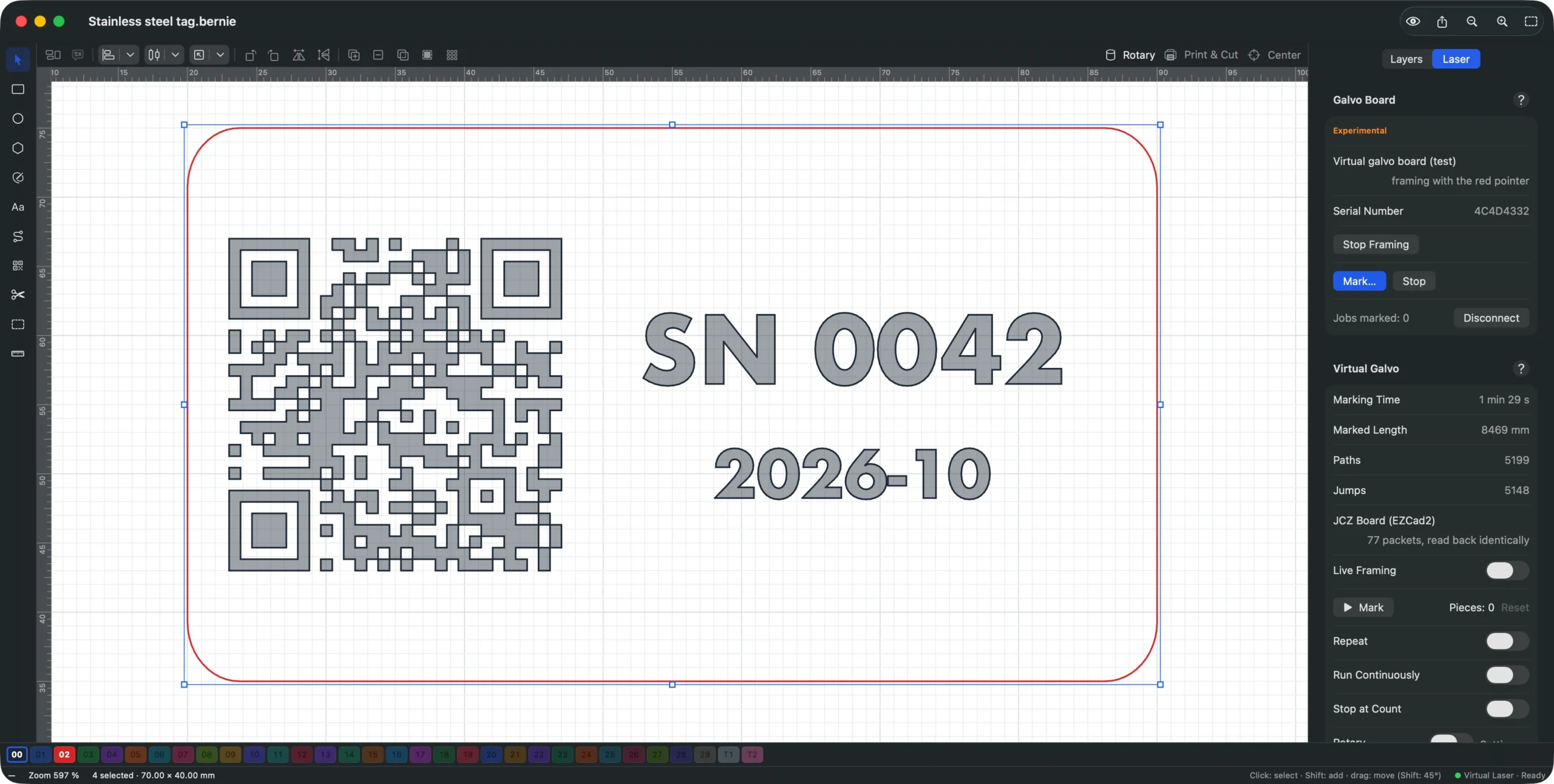
--galvo: also for iPad and iPhone, Use Bernie Link Board). Close EZCad, plug in the board, Connect to the Board… (in the browser, pick it in the window that opens). Frame (Red Pointer) traces the framing chosen for the virtual galvo in a loop, laser disabled; Mark… (after framing if the device requires it) asks a safety question, then marks the job as the virtual galvo computes it; Stop stops at once (laser disabled, pointer off), including a confirmed marking that has not started yet. Rotary, external axis and repeated marking are not driven yet: turn them off. On Windows, the board must use the WinUSB driver (Zadig tool) instead of the EZCad one (reinstall the EZCad driver to go back); on Linux, the.debpackage installs the access rule (60-bernie-galvo.rules, plug the board in again); with the AppImage, copy it to/etc/udev/rules.d. Bernie has not yet been tried on a real board: stay near the machine, with suitable glasses and the enclosure closed. - Laser panel: the JCZ Board (EZCad2) line gives the number of 256-command packets the driver would send and checks that a virtual board, reading them back, goes through exactly the marking positions; the virtual galvo computes the job’s marking — duration, length actually marked (wobble included), marks, jumps — flags points outside the field and draws it: marks in black, jumps dotted, framing in red (none, bounds, convex hull or exact contour: the path the red pointer would follow to place the part). Options: frame each shape (bounds, hull), outside shapes only (contour, without letter insides or holes), tool layers only (frame the templates on layers T1 and T2, never marked, instead of the job). In contour mode, a filled area or an image is framed by its hull, not line by line.
- Bernie Studio and desktop app: the Galvo laser box of the Device window (device name in the status bar), same settings and same layer settings; the Laser tab shows the virtual galvo.
This manual is also built into Bernie: press F1, or open the Help menu, to read the topic for what you are doing. A mistake, a missing answer? Tell us
Try it in Bernie, for free.
Free laser engraving and cutting software for diode, CO2, fiber and galvo lasers. Windows, Mac, Linux, iPad, iPhone and in the browser.